How Additive Manufacturing and CT Inspection Are Transforming Implantable Medical Devices
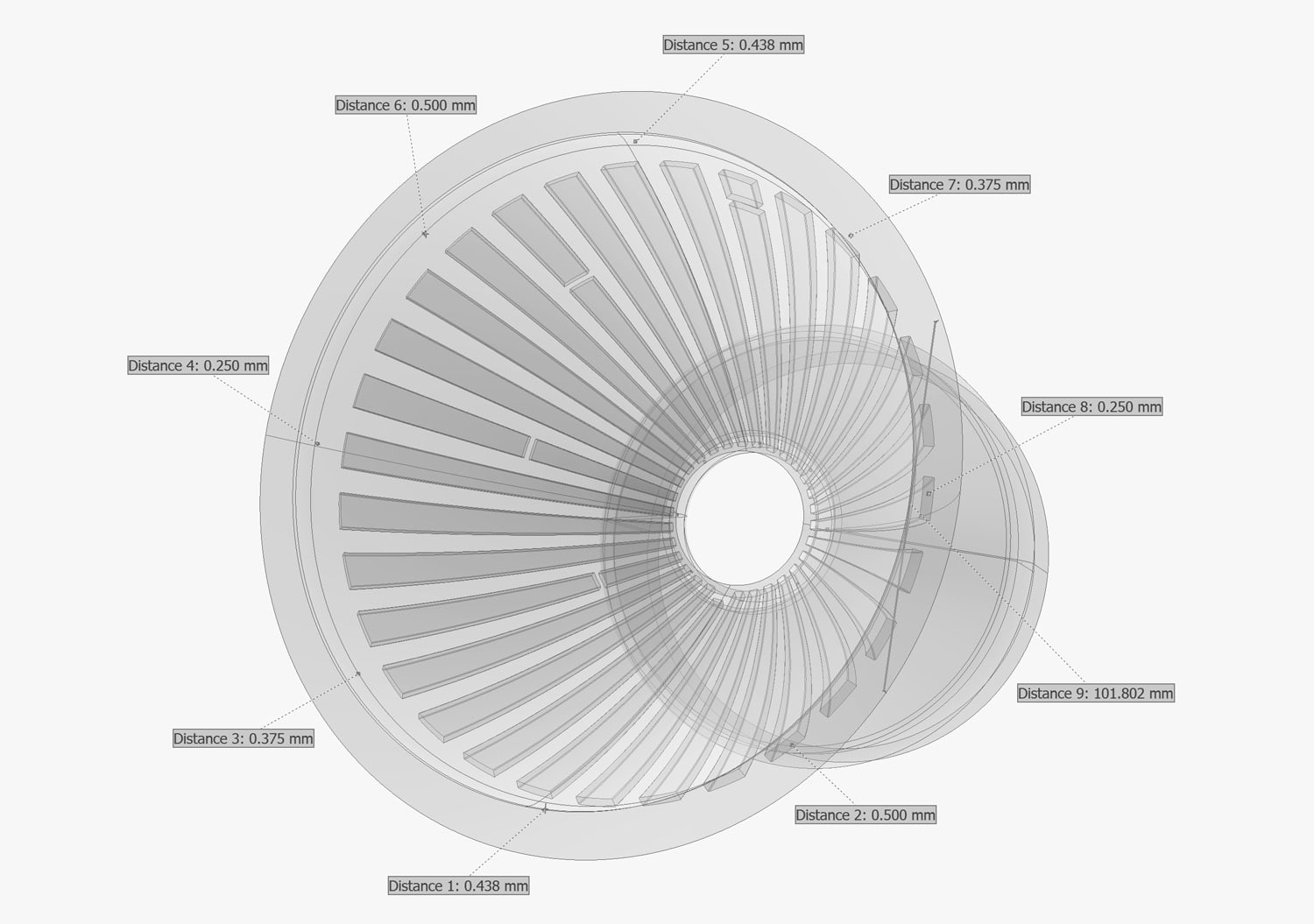
Additive manufacturing (AM) lets medical device makers print implants with porous, bone-like lattices and patient-matched shapes that machining cannot produce. Because those features are internal and complex, industrial computed tomography (CT) is the most complete way to inspect them: it finds porosity and lack of fusion, measures hidden lattice struts and walls against CAD, and produces the objective evidence regulators and quality teams need.
Spinal cages, acetabular cups, knee components and cranial plates printed in titanium are now routine in orthopedic surgery, and the same technology also produces surgical instruments, dental restorations and external prosthetics. What makes these parts clinically valuable, their internal complexity, is exactly what makes them hard to inspect. While AM is used routinely now for implantable devices, the quality risks it introduces are real but using industrial CT scanning closes the inspection gap from R&D through production.
How is additive manufacturing used for implantable medical devices?
Additive manufacturing builds a part layer by layer from a digital file, such as a CAD model or a patient’s CT or MRI data. For implants, that digital starting point is the advantage: designers can embed lattices, change sizes without new tooling, and match an implant to a patient’s anatomy.
| Process | Typical materials | Common implant applications |
|---|---|---|
| Laser powder bed fusion (L-PBF) | Ti-6Al-4V ELI, CP titanium, cobalt-chrome | Interbody spinal cages, acetabular cups, tibial trays, patient-matched plates |
| Electron beam powder bed fusion (EB-PBF) | Ti-6Al-4V ELI | Porous acetabular cups, augments, large lattice structures |
| Material extrusion and polymer powder bed fusion | PEEK, PEKK | Cranial and maxillofacial implants |
| Vat photopolymerization | Biocompatible resins | Surgical guides, trial implants, anatomical models |
Titanium dominates because it combines biocompatibility with strength. ASTM F3001 sets requirements for Ti-6Al-4V ELI parts made by full-melt powder bed fusion, covering feedstock, chemistry, microstructure, mechanical properties, hot isostatic pressing and inspection.
Why do implant makers choose 3D printing?
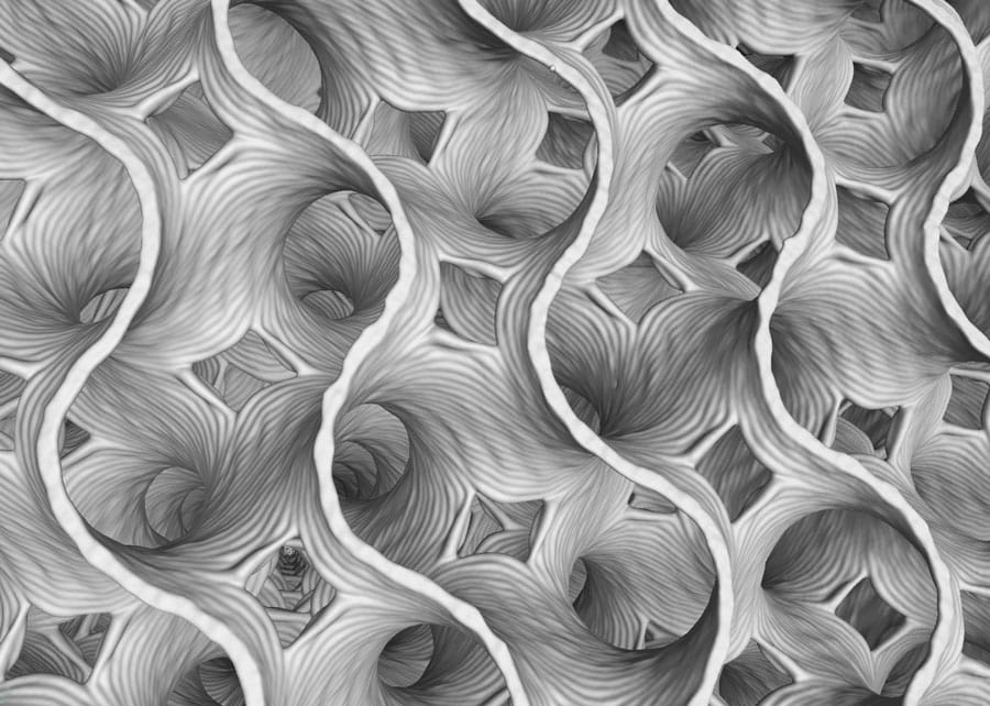
The main reason is the porous lattice. Solid Ti-6Al-4V has an elastic modulus of roughly 110 GPa, while cortical bone sits around 10–30 GPa. That mismatch causes stress shielding: the implant carries the load, and the bone around it can weaken and resorb. Printed lattices lower the effective stiffness and give bone a scaffold to grow into.
- Osseointegration. Interconnected pores encourage bone ingrowth and biological fixation, which supports faster healing without the stress shielding seen with solid metal implants.
- Tunable stiffness. Pore size, strut diameter and topology can be graded across a single implant, so its stiffness can be tuned to better match the surrounding bone.
- Patient-matched devices. Implants can be sized to patients within approved design specifications, which FDA treats differently from true custom devices.
- Part consolidation and speed. Solid and porous regions print as one piece, eliminating sintered beads or sprayed coatings and shortening development cycles.
What quality risks are unique to 3D-printed implants?
The features that make AM implants work well are the ones that make them hard to verify in terms of quality. Layer-wise melting creates flaw types that differ from castings and forgings, and many of them sit deep inside a lattice where no probe or camera can reach.
| Risk | What causes it | Why it matters for an implant |
|---|---|---|
| Gas and keyhole porosity | Entrapped gas, excess energy input | Reduces fatigue strength in load-bearing regions |
| Lack of fusion | Insufficient energy, spatter, recoater issues | Planar voids act as crack initiators |
| Trapped or partially sintered powder | Fine pores and closed cavities | Loose particles can release in the body; affects cleaning validation |
| Strut and wall deviation | Thermal distortion, melt-pool variation | Changes porosity, stiffness and ingrowth from the design intent |
| Surface roughness | Adhered particles, stair-stepping | Affects fatigue and the bone–implant interface |
| Inclusions | Contaminated or reused powder | Unexpected material in a permanent implant which can lead to a number of biological problems |
ASTM E3166 notes that porosity, lack of fusion, skipped layers, inclusions and excessive roughness can degrade strength and fatigue properties. For a permanent implant cycling millions of times a year, those are not cosmetic issues.
How does industrial CT inspect additively manufactured implants?
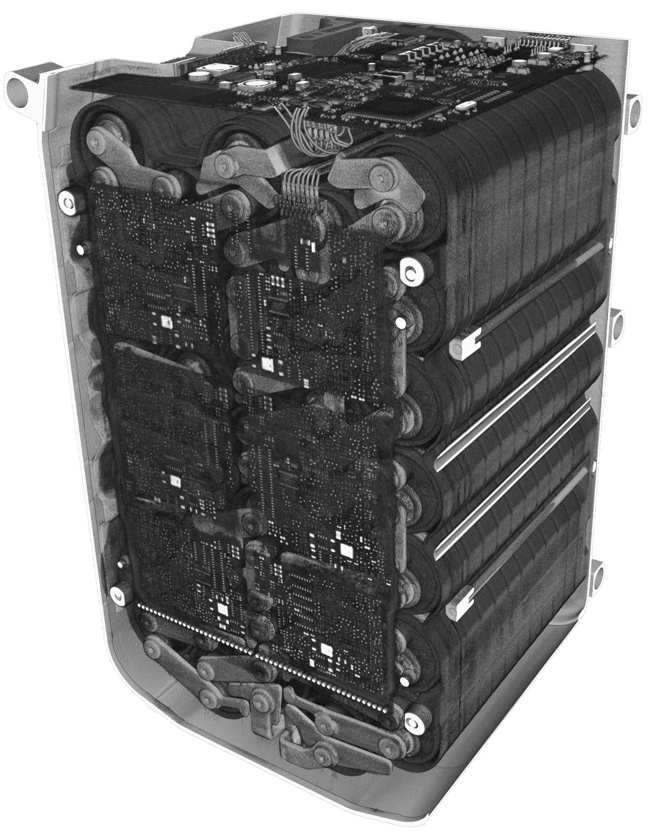
Industrial CT captures hundreds to thousands of X-ray projections as the part rotates, then reconstructs a full 3D volume of every voxel inside it. Unlike penetrant, ultrasonic or 2D radiography, CT sees the entire lattice, every internal channel and every closed pore in one nondestructive scan.
What one CT scan can tell you about an AM implant:
- Porosity and defect analysis. Locate, size and classify voids, lack of fusion and inclusions, with volume-percent porosity reported by region (solid core versus porous shell).
- Lattice characterization. Measure strut thickness, pore size and pore interconnectivity, and compare actual lattice porosity to the design value.
- Trapped powder detection. Find unfused powder and closed cavities that cleaning cannot reach.
- Dimensional metrology. Measure internal and external features, including wall thickness, without sectioning the part.
- Nominal-to-actual CAD comparison. Overlay the scan on the CAD model as a color deviation map to catch distortion and build-orientation effects.
- Surface texture. Extract surfaces directly from the volume to quantify roughness on features a profilometer cannot touch.
- Failure analysis. Investigate returned or fatigue-tested parts without destroying the evidence.
Resolution and penetration have to match the part. Small spinal cages and dental components benefit from microfocus CT for fine strut detail, while large, dense titanium or cobalt-chrome components may need higher energies. NSI’s efX-CT software handles reconstruction, measurement and surface extraction, and add-ons such as SubpiX and VorteX push resolution and scan quality further. NSI has applied VorteX to fine medical features in its stent micro-CT study.
Where does CT fit in the AM implant lifecycle?
CT is most valuable when it is used at every stage, not only as a final gate. The same scan data that guides a design change in R&D becomes the baseline for validation and production acceptance.
- Design and R&D. Verify that printed lattices match the designed pore size and strut thickness; compare build orientations and parameter sets; feed real geometry into finite element models.
- Process development and validation (Installation Qualification, Operational Qualification, and Performance Qualification). Quantify porosity across build plates and positions to establish worst-case locations; confirm the effect of Hot Isostatic Pressing, heat treatment and powder reuse.
- First article inspection. Perform full nominal-to-actual comparison and internal metrology before releasing a new design or build file.
- Production monitoring. Scan sampled or 100% of parts against acceptance criteria. Automated loading, such as NSI’s RobotiX systems, makes higher-volume CT practical.
- Post-market and failure analysis. Examine explants and fatigue specimens nondestructively to find root cause.
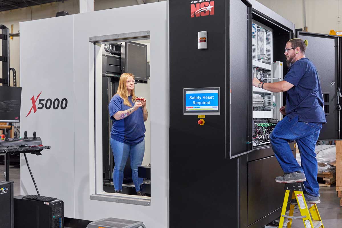
Teams can do this in house with a system such as the X3000 or X5000, or outsource to NSI’s X-ray and CT scanning services during development or for overflow capacity.
What do FDA and the standards bodies expect?
FDA’s final guidance, Technical Considerations for Additive Manufactured Medical Devices (December 2017), covers any device with at least one additively manufactured component. It is organized around design and manufacturing considerations and device testing considerations, and it supplements device-specific guidance rather than replacing it. In practice, manufacturers are expected to understand how each step of the AM workflow affects the finished device and to validate processes whose output cannot be fully verified, which is where volumetric inspection data becomes valuable. That guidance predates FDA’s Quality Management System Regulation (QMSR), which took effect in February 2026 and aligns with ISO 13485:2016, so manufacturers should check the QMSR for current quality system requirements.
| Standard | Scope | Relevance to CT |
|---|---|---|
| ASTM F3001 | Ti-6Al-4V ELI by powder bed fusion | Material and inspection requirements for titanium implants |
| ASTM E3166 | NDT of metal AM parts after build | Section on CT, including microfocus CT; flaw–property correlation |
| ASTM F3624 | Surface texture of metal PBF parts | Includes XCT among surface measurement methods |
| ASTM E1695 | CT system performance | Verifying the CT system itself |
| ASTM Committee F42 | Additive manufacturing technologies | Ongoing work items on CT porosity and dimensional measurement |
E3166 was written with aerospace parts in mind, but its flaw classes and CT guidance translate directly to implants. ASTM F42 also has work items in progress on traceable CT porosity measurement and CT dimensional measurement of AM production parts. NSI engineers contribute to ASTM E07 and F42 committees, as described in NSI’s AM inspection case study.
How North Star Imaging supports AM implant quality
North Star Imaging has built industrial DR and CT systems since 1986 and supports medical device manufacturers from first prototype through production. Teams can work with NSI in three ways:
- CT systems. Cabinet systems from the X25 to the X7000, plus automated RobotiX configurations. Browse the full CT systems overview.
- Inspection services. Send parts to NSI’s labs for CT scanning or, for very dense or large parts, high-energy CT. It is a fast way to qualify a new lattice or settle a supplier question before investing in a system.
- Software and training. The efX software suite and X-ray University training help teams build repeatable, documented inspection procedures.
See more examples on NSI’s medical device applications page and additive manufacturing applications page.
Ready to see inside your implants? Talk to an NSI CT expert about scanning a sample lattice cage, acetabular cup or patient-matched part.