Seeing Both Sides: DR and CT Inspection of Multi-Material Assemblies
Walk through any modern manufacturing floor and you’ll find fewer and fewer parts made of one material. An EV battery module stacks copper busbars, aluminum housings, polymer separators and adhesive. An aerospace bracket joins a carbon-fiber laminate to a titanium fitting with steel fasteners. A drug-delivery device wraps a stainless needle and a tungsten marker inside molded polypropylene. A power module bonds copper, solder, silicon and encapsulant into a single stack.
These assemblies are a design win and an inspection headache. The moment you put a high-density metal next to a low-density composite and ask a single X-ray scan to resolve defects in both, you run straight into the physics.
Why one scan struggles to serve two materials
X-ray attenuation is exponential, and it scales steeply with density and atomic number. A few millimeters of steel or copper can attenuate a beam by orders of magnitude more than the same path length of carbon fiber, polymer or foam. That difference shows up as a raw signal problem at the detector.
Set your technique to penetrate the metal and the composite regions go straight to saturation – every low-density feature washes out into a uniform bright field with no usable contrast. Back the technique off to bring detail into the composite and the metal becomes photon-starved: the transmitted signal falls into the detector’s noise floor, and you’re reconstructing noise rather than material.
A 16-bit detector nominally offers about 65,000 gray levels, but usable dynamic range is always smaller than the bit depth suggests once electronic noise, offset drift and quantum noise are accounted for. Multi-material assemblies routinely demand more range than a single exposure can deliver.
The dynamic range squeeze is only the headline problem. Several secondary effects pile on:
- Beam hardening. Industrial X-ray tubes emit a polychromatic spectrum. Low-energy photons are absorbed preferentially, so the mean beam energy shifts upward as it travels through material. Because attenuation is energy-dependent, projection values stop being a linear function of thickness – and linear reconstruction algorithms respond with cupping and streaking artifacts.
- Scatter. Dense components can have high amounts of Compton Scatter. That scattered radiation lands on detector regions that should be reading low-attenuation signal, adding a haze that flattens exactly the subtle contrast you need in the composite.
- Photon starvation streaks. Along the longest metal paths, so few photons reach the detector that the reconstruction produces dark bands and bright streaks radiating from the metal – often straight through the adjacent composite region you were trying to inspect.
- Detector lag and blooming. Saturated pixels don’t reset instantly. Their signal bleeds into neighboring pixels and into subsequent frames, distorting edges near metal-to-composite interfaces.
- Segmentation failure downstream. A global ISO-50 threshold is meaningless in a volume with three or four material densities. Automated porosity, wall thickness and CAD-comparison routines built on a single surface determination will simply produce the wrong numbers.
The defects you’re hunting sit on both sides of the divide and can be hidden by artifacts and improper technique. In composites, this may hide delaminations, porosity, resin-rich zones and fiber waviness – low-contrast features that need excellent contrast-to-noise ratio (CNR). In metals this may hide cracks, inclusions, lack-of-fusion and incomplete braze – features that need penetration first and contrast second.
Overcoming the imbalance
There is no single setting that solves this. What works is a layered strategy that starts at the technique sheet and continues through reconstruction and analysis.
- Optimize the technique before reaching for algorithms
Choose kV based on the thickest, densest path through the part – then add physical prefiltration (aluminum, copper, tin or brass at the tube port) to pre-harden the beam. Filtration strips out the low-energy photons that would otherwise be absorbed in the first interactions with the metal and contribute nothing but artifacts. The trade-off is honest and unavoidable: a harder beam means less subject contrast in the low-density material and lower flux, which you pay back in exposure time. Higher mA, longer integration and frame averaging buy back signal-to-noise in the starved regions.
- Fix the geometry problem with orientation and compensators
Path length through metal is something you control. Rotating or tilting the part so that dense features never align along a ray path – and never stack with each other – can eliminate artifacts that no algorithm will fully recover. Compensating filters, beam-shaping masks or moldable attenuating putty packed around thin sections equalize path lengths across the field of view and pull the whole projection into the detector’s usable range.
- Match the detector to the job
Flat panel detectors give you speed and area. Linear diode arrays, with source-side and detector-side collimation, give you dramatically better scatter rejection and dynamic range on very dense assemblies – at the cost of scan time. Rigorous offset, multi-point gain calibration and bad-pixel mapping at the actual operating technique matter far more here than in a single-material scan, because you’re asking the detector to behave linearly across its entire range.
- Consider multi-scan and multi-energy strategies
Some assemblies simply want two scans: a high-energy scan tuned for the metal and a low-energy, region-of-interest scan tuned for the composite, registered and reviewed together. Dual-energy acquisition takes this further, using the difference between two spectra to help separate materials. Dual-tube systems make this practical by putting a microfocus tube and a higher-power minifocus tube in the same cabinet.
- Correct in reconstruction
Modern reconstruction pipelines contribute real gains: beam-hardening correction, ring artifact reduction and other algorithmic image enhancements. Helical acquisition also helps by reducing cone-beam artifacts on elongated assemblies and improving sampling of horizontal interfaces – exactly where composite-to-metal bond lines tend to live.
- Analyze per material, not per volume
Use local adaptive surface determination so each material interface gets its own threshold. Segment by region, run porosity and void analysis inside the composite domain, run crack and inclusion review inside the metal domain, and compare each to CAD separately. Then document the recipe so the next operator reproduces it.
How North Star Imaging tackles multi-material inspection
North Star Imaging (NSI) has spent decades building systems and software around exactly these hard applications – aerospace, automotive, electronics, medical devices, EVs and batteries, castings and additive manufacturing.
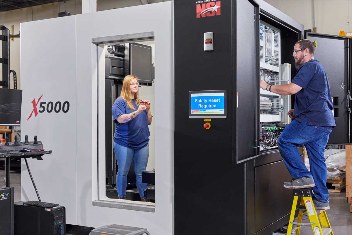
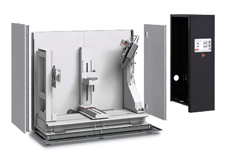
On the hardware side, NSI’s X-series systems are built for flexibility rather than a single sweet spot. Platforms such as the X5000 and the larger X7000 cover energies from 10 kV to 450 kV with nano-, micro- and minifocus tube options, and both support an optional dual-tube configuration – commonly a 225 kV microfocus tube paired with a 450 kV minifocus tube – so a facility can scan a thin polymer housing and a dense metal casting in the same cabinet without compromising on either. NSI partners with essentially all major industrial detector manufacturers, offering flat panels up to 17 inches and linear diode arrays up to 36 inches, which lets an application engineer pick scatter rejection and dynamic range over raw speed when the assembly demands it. Where energy is the limiting factor, the MeVX series brings linear accelerator sources up to 9 MeV into the same easy-to-use format, running the same efX software suite.
On the software side, NSI’s proprietary efX suite is where much of the contrast-imbalance work happens. efX-DR provides live averaging, live histogram and multiple image measurement tools. Image analysis prior to acquisition is critical prior to multi-material work. efX-DR also provides image offset with multiple gain calibration and defective pixel correction, so the detector is characterized properly across its full range before a single projection is stored. NSI’s advanced scanning modalities address the geometric side of the problem: SubpiX shifts the detector by fractions of a pixel to split each pixel into quadrants, cutting the voxel size in half while also improving contrast-to-noise ratio and signal-to-noise; MosaiX stitches detector positions into a large virtual detector so magnification isn’t sacrificed to fit the part; and VorteX helical acquisition moves the part or the source and detector vertically to scan elongated assemblies while suppressing standard cone-beam artifacts. Layered frames let operators evaluate multiple frame-averaging settings from a single acquisition rather than rescanning, and ring reduction cleans up detector-driven artifacts that can cause improper product evaluation.
The recently released efX 3.0 rebuilds the efX-CT experience around a project-based architecture, saving datasets, annotations and analysis states into a single shareable file. It adds multi-volume comparison for analyzing multiple parts or scans in one session, preview surfaces for fast estimation before full computation, expanded 2D and 3D annotation, global clipping objects, and a unified docking interface. It also supports ASTM E1695, which matters for anyone operating under a regulated inspection procedure. Reconstruction runs on GPU developed specifically for NVIDIA hardware, and features like live focal spot measurement help operators hold geometric unsharpness within tolerance – a prerequisite for resolving fine composite features next to dense metal.
For teams who need results before they need capital equipment, NSI also operates inspection service labs and runs X-ray University™ training for operators who want to build technique-development skill in-house.
Multi-material assemblies aren’t going to get simpler. The parts that make products lighter, denser and more capable are exactly the parts that punish a single-technique scan. Getting good data out of them is a matter of pairing the right source, detector and scanning modality with software that lets you extend range, correct artifacts and analyze each material on its own terms.
Talk to Our Experts