Computed Tomography Used in Reverse Engineering
Computed Tomography (CT) is an intricate and dynamic tool and its usage covers a wide range of testing capabilities – from inspection of components for both internal and external measurements, to detection of defects and discrepancies produced during the manufacturing process. Additionally, an important aspect of CT is that it can also be used for creating a model or drawing for reverse engineering purposes.
Reverse engineering is not necessarily carried out to duplicate the part, but for analytical and testing purposes. It can be used for replicating worn parts, or converting physical models to digital ones. However, although this process is very common in the industry, it is not necessarily easy.
Common challenges facing reverse engineering include many different types of equipment that may not be available, and not having the proper software and personnel to carry out the complex tasks. The modern-day test lab consists of multiple teams of engineers, all with specific tasks to carry out during the reverse engineering process. Pair this with the need for multiple pieces of equipment to complete the testing, then the process can become quite time consuming. With CT, producing the data necessary to solve the most intricate and complex component and assembly designs is a much quicker process.
Similar to CAT scanning that is used in the medical field, CT utilizes different imaging techniques to produce data – the difference being that CT collects a significant number of images, while the specimen rotates 360°, as opposed to CAT scanning where the gantry rotates around the specimen.
In using software, the images are reconstructed to a 3D volumetric digital model. The data is stored as a point cloud set to a numerous number of formats (.STL, . OBJ, .PLY, etc). The process can continue with modeling into another suitable format such as a triangular mesh, a set of NURBS surfaces, or a parametric CAD model.
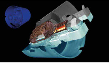
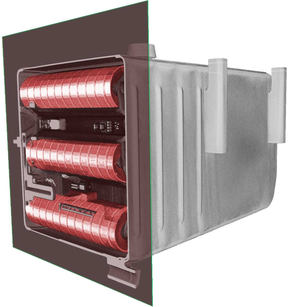
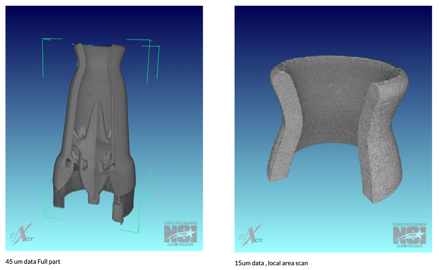
In one application, North Star Imaging used a windshield wiper motor pump. The individual component is CT scanned to optimize resolution. The data of the scan is represented by voxels, or 3D pixels. This voxel size is directly correlated to the resolution of the scan. Simply put, the closer the object to the x-ray source and the further the detector (imaging sensor), the better the resolution.

A key factor to remember is the object still needs 360° of rotation during imaging. Using CT software, once the component is scanned, the collected data is gathered into one workable volume. From this volume, the software allows manipulation of the model. Reference measurements and sections of the part are just some of a few tools at the operator’s disposal when analyzing the collected data. At this point, surfaces can be created as well by placing a wire mesh to define the features of the model.


