Producing an Additive Manufactured Replica using CT Technology
Computed Tomography for Reverse Engineering
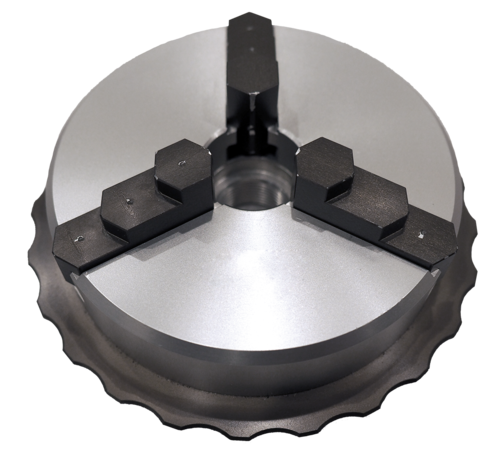
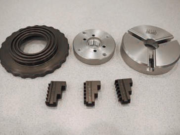
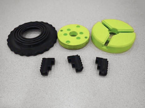
We scanned an Aluminum 3 Jaw chuck to reproduce a plastic (AM) replica. To do this we had to first disassemble the metal chuck and scan the pieces. Then we proceeded to reconstruct and surface all components. Using stl. polygon data in the AM printer, we produced the parts. Then we scanned all of the AM (plastic) components and produced stl. Data. After producing the stl. data, we used stl. polygon data in Volume Graphics to get dimensional verification.
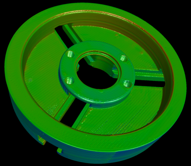
Here are the images of the 3 Jaw chuck fixture we scanned. It was disassembled prior to scanning. You can scan assemblies together and separate the pieces in the scan data, but it is significantly more time consuming, assuming good penetration for surface data.
When developing a quality technique, you must follow these guidelines:
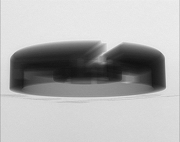
- X-Rays must penetrate the entire sample at all angles without over exposing the detector.
- The images must have enough contrast to see internal structures (holes, passageways, etc..)
- Scan at a resolution that is suitable for the size of features that you want to capture
Voxel data of the scanned samples will be surfaced. The surface data can be exported as .stl, .ply., obj., files (and many more). Then measurements can be made from the surface data to verify dimensions.
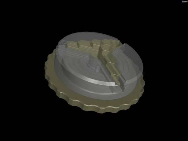
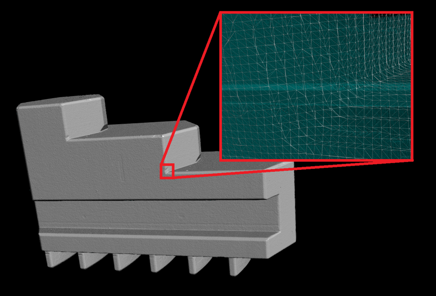
The software creates a point cloud from the voxel data at a specific iso (gray) value. Points are created at sub-voxel positions based on neighboring voxel gray values. The point cloud files from CT scan data may need to be decimated before loading into printer software as the files are very large.
Just one of the jaws was over 4.3 million points resulting in a 415 MB stl file! So the file was decimated down to 5 MB for printing.
The .stl files were loaded into the printer software and printed.
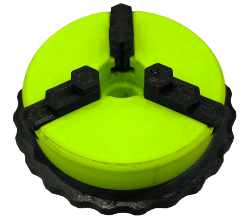
The printed samples can then be CT scanned to verify dimensional accuracy of the printing process.
Once the printed sample has been scanned measurements can be made to verify dimensions.
The sample must have a surface determination to preform measurements. The geometric features are fit to the surface (planes, cylinders, spheres) and measurements are made from the features. The fit points for features can now provide information about the geometry of the sample.
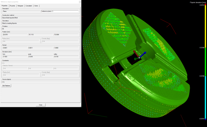
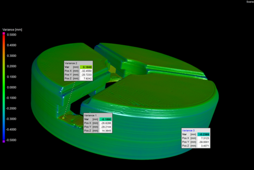
The scan data can also be compared to the CAD model or .stl file to see deviations.
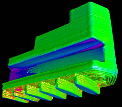
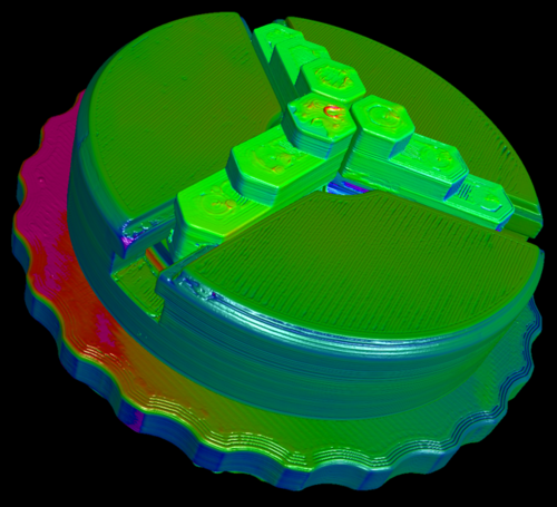
A CAD model or point cloud data can be loaded into the CT software. The software can preform a best fit, best fit with reference objects, or a 3-2-1 alignment of the scan data to the CAD/point cloud data. A surface of the scan data is compared in 3D against the CAD and assigned colors based on deviation. Annotations can be placed on the 3D model to give specific details about a local area.