Using CT Scanning to Improve the Integrity of Motors
Computed Tomography for Motors
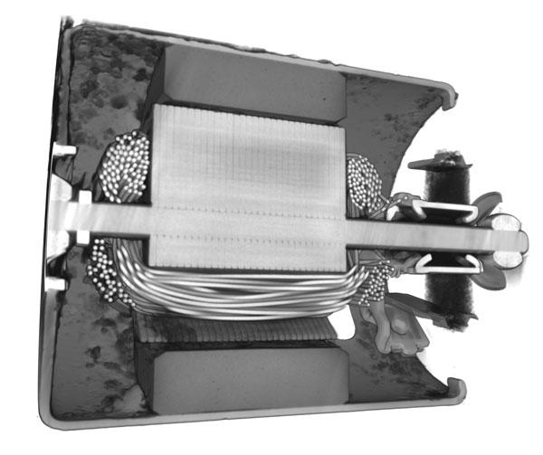
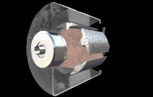
X-ray inspection is often used with complex assemblies like this failed pump motor. When inspecting this motor, we looked at multiple components to identify the reason for failure.

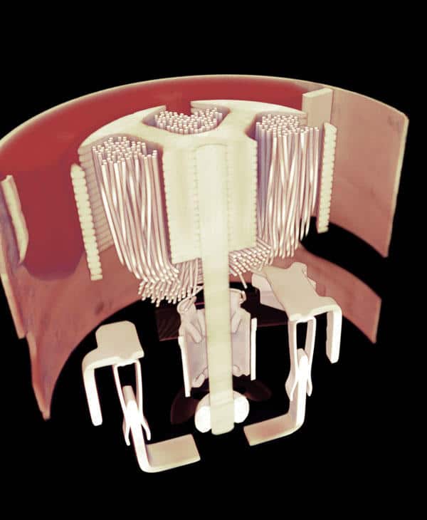
The brushes have a charge and as it spins it’s charging contact pads and transferring the positive and negative to make it spin. Once the brushes wear out, they are unable to make contact which can result in failure.
Check for FOD (foreign object debris) which could be a piece of metal, plastic, or anything that could be detrimental to performance. FOD may be seen in the wires, solder blobs, or drip spatters.

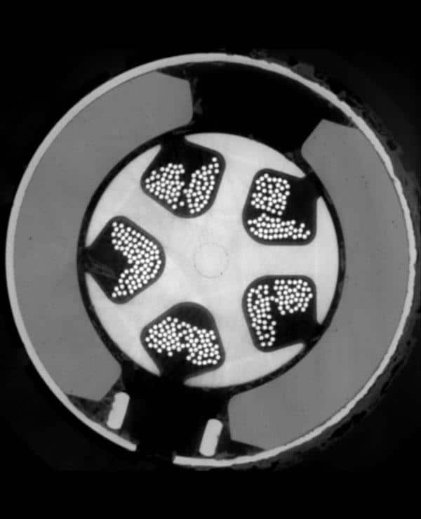
Wire placement is also a consideration. The winding needs to be wound on the stator correctly. If a wire is wound incorrectly it would cause poor performance or a nonfunctional motor.
The motor has two stabilizer points. The shaft sits on the stabilizer points and acts as a bearing to keep the spinning balanced. If the motor only had a stabilizer point on one side, it would shake and cause damage.
The motor drives a pump and when it spins it will pump out fluid. If the nozzle tip or inlet hose is clogged it would not function correctly.

Different types of motors have planetary gears built into them to reduce the speed and gain torque. The output speed and torque power can be changed. CT can be used to look for broken gears. If one of the teeth break off and get stuck in the gear it will stop it. Watch this 4D video of one gear rolling over the FOD to see an example.
The reason this particular pump failed is due to the oxidation or rust preventing the assembly’s motorized pressure pump from moving fluid from its reservoir to the hoses and nozzles that deliver the fluid.
