3D CT Reconstruction Applications in the Metal Casting Industry
Computed Tomography for Castings
CT scans nondestructively provide excellent resolution internally and externally, which then allows for measurement on surfaces both inside and outside an object. Also, due to the penetration of X-rays, CT scans are unaffected by certain object characteristics such as dark, reflective or transparent surfaces and/or shaded zones on the item that can cause difficulty with other 3D scanning methods. Furthermore, 3D CT reconstruction models can be directly compared to CAD models in order to display differences or commonalities.
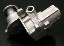
The pictured Exhaust Gas Recirculation (EGR) housing for car and truck diesel engines was cast by TCDC. The part is composed of an aluminum casting and two integrally cast stainless steel inserts. The project’s three main objectives were to measure the part, inspect for internal integrity, and dimensionally compare the actual manufactured casting with the originally designed CAD model.
he following images show the 3D CT reconstruction of TCDC’s aluminum casting. The model can be manipulated in real time 3D and it is also possible to slice through in any direction for internal inspection. The reconstruction process consists of complex algorithms that transform the stack of 2D X-ray images to a 3D volume model. 2D measurements such as length, diameter, angle, etc. can be applied to a slice generated from the cutting plane of a 3D volume. Now we can measure any feature, part or even defect inside a structure or an assembly without destroying it.
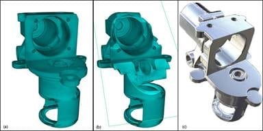
The 3D CT reconstruction can also be transformed to a surface model. A threshold value of radio density is chosen by the operator and set using edge detection image processing algorithms. From this, a 3-dimensional model can be constructed and displayed on screen. Typically, models are composed of thousands of polygons up to 50 million polygons. Image (c) shows a surface reconstruction with a reflective surface. With the generated surface model, many different applications become available to the user. The output format (points cloud, STL, WRL …) is compatible with most CAD software for Reverse Engineering applications, rapid prototyping machines for modeling, Finite Element Analysis software for simulations, etc. In most cases, the polygon mesh generated by the CT system can be used in the above applications without modification and typically, the resolution is higher than needed. However, in order to modify or take measurements of the CT surface model with a CAD software, the CT model needs to be processed to make it editable. Modeling software (e.g. Geomagic, Rapidform, Polyworks) propose semi-automatic tools to transform the polygon mesh to Nurbs Surfaces and parametric CAD models.
Comparing 3D CT Image to CAD Model
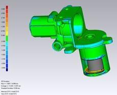
Dimensional analysis is one key available application for model comparison. Since CT provides very accurate dimensions on surfaces, the technology is often used for metrology studies. Measurements can be done either directly on the surface using any CAD or Metrology software, or it can automatically compare the CT model with the CAD model, or even the CT model with another CT model. For TCDC’s casting application, no post processing was needed on the polygon mesh. The CT surface file was directly compared with the dimensions of any other surface model, verbatim or solid. Comparison of a 3D CT model reconstructed by NSI with a CAD model created by TCDC. The examples above show a dimensional comparison between the Solidworks CAD model of the part provided by Twin Cities Die Casting, and the CT surface reconstruction created by NSI.
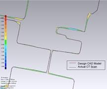
Once the two models are aligned, a simple 3D comparison option automatically creates a colored view showing all the dimensional differences between the two models. In the example above, all the dimensional differences between the Solidworks model and the actual CT surface (polygon mesh) are represented by colors. Tolerances between -0.300mm and +0.300mm are shown in green. Yellow denotes the areas where the CT scan measurements are larger than the original CAD model and blue indicates smaller measurements. It is possible to change tolerance values and the color code to cater to a specific project or preferences. Numerical values are an available option as well. 3D CT is now more accessible than ever for the foundry industry as a viable tool; user-friendly interfaces, increased scan speeds, and decreasing prices have all attributed to the rapid growth of this technology. Having very accurate internal dimensions without destroying the item, along with the ability to compare to a reference model is entirely unique to CT. There are no shaded zones, it works with all kinds of shapes and surfaces, there is no post-processing work needed and the resolution is excellent. Above all, the greatest benefit is the ability to nondestructively obtain the 3D internal structure of the object, and CT is the only technology capable of achieving such performance.
Talk to Our Experts