An Introduction to CT Scan Image Artifacts
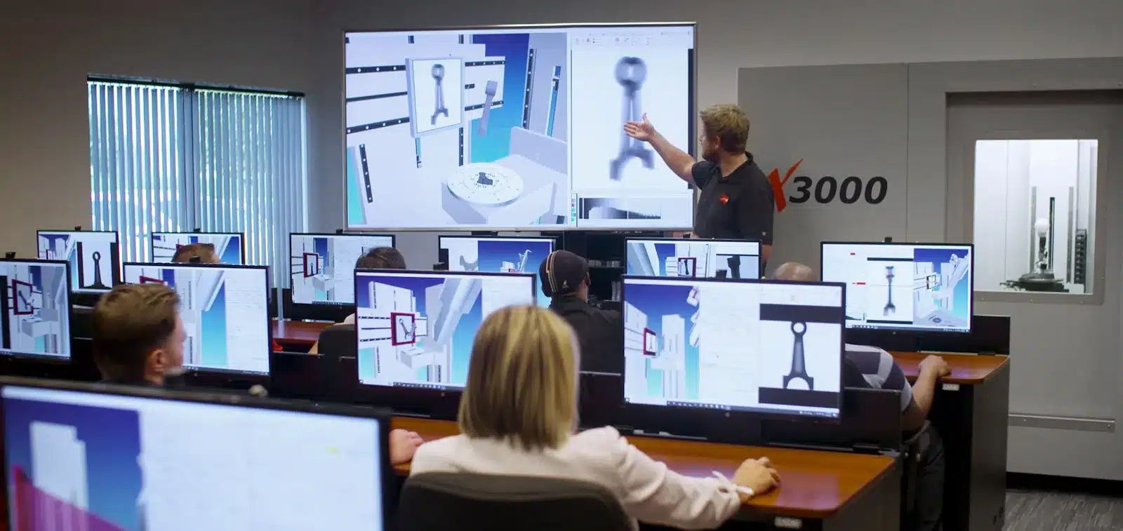
There is no denying that a high resolution industrial X-ray Computed Tomography (CT) system is indispensable to any cutting-edge analysis lab that specializes in either non-destructive or destructive analysis techniques. However, one thing that can set back even the best CT analyst is when there are irritating CT image artifacts obscuring the areas that you are most interested in evaluating for defects. While there are a few ways to minimize image artifacts, they can be an unfortunate reality and it pays off to understand the different forms they can take.
What is an Image Artifact?
At the most basic level, a CT image artifact is any discrepancy between the reconstructed values in a CT image and what is expected based on the material density and the sample geometry. They typically manifest themselves as bright or dark streaks or shadows that usually follow some sort of predictable pattern as shown in Figure 1 below.
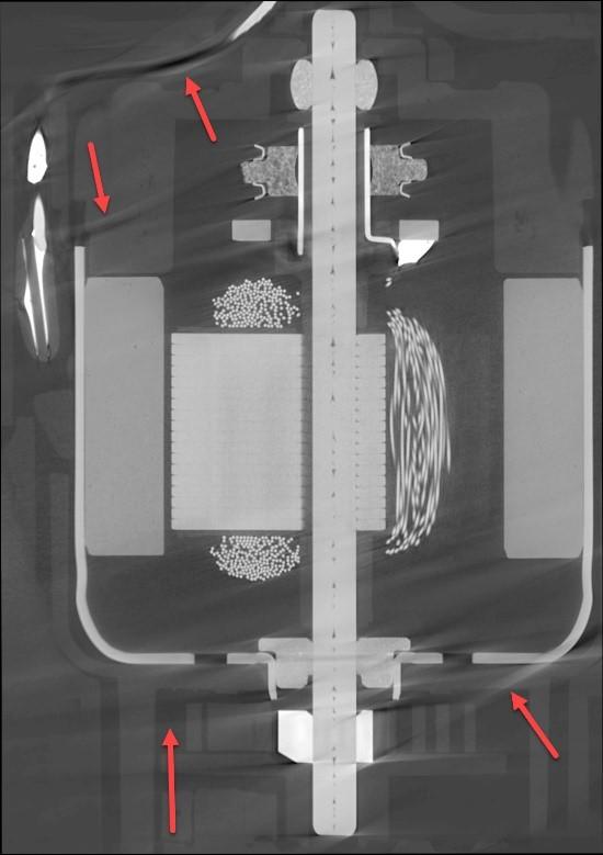
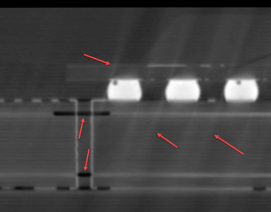
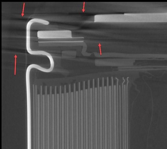
Figure 1: Red arrows indicate examples of CT image artifacts
What Causes CT Image Artifacts?
There are two primary categories of artifacts: ones caused by problems with the CT imaging setup (E.g. ring artifacts, under-sampling aka aliasing, sample movement, etc.) and secondly ones that are more sample dependent such as beam hardening, scattered radiation, and lack of x-ray penetration. This article will focus mainly on the second category because the first group can be virtually eliminated by use of proper scan technique and fixturing.
Sample-dependent artifacts can be the most frustrating because their effect can be reduced but not always eliminated using the optimal CT technique parameters and software corrections. Oftentimes the most prominent artifacts tend to be due to a phenomenon called beam hardening.
Beam Hardening – the Abridged Version
To begin, it is important to understand that the x-ray photons coming from a tube consist of a full spectrum of x-ray energies, not just the voltage that the tube is set at. For example, even if a tube is set for 225kV, most of the photons are coming out at lower energy levels around 50-100keV. Secondly, every sample material has its own coefficient of attenuation which depends on the energy of the x-ray photons going through it. When an x-ray beam begins to penetrate any given material, the lower energy x-rays will be preferentially attenuated and the x-ray beam spectrum becomes harder (averages a higher energy).
Most modern CT reconstruction algorithms can adequately adjust for the non-linear beam hardening effect within a single material but things become much more difficult when there are multiple densities of materials within a single scan volume. This is where the streaks and shadows come from when trying to image both very high and very low density materials in the same scan.
Adjusting the CT Technique to Minimize Beam Hardening Artifacts
As a rule, the harder the x-ray beam (i.e. the higher the average energy), the less beam hardening will affect the resulting CT scan images. This can be most easily accomplished by using a higher tube voltage or adding physical filters such as copper or brass onto the face of the tube. Sometimes repositioning the sample to minimize how much the densest regions overlap each other can help tremendously, as can running a helical scan instead of a standard cone beam scan. However, there tends to be a limit to how much this helps the overall image quality because raising the voltage or adding filters has the sometimes unwanted side effect of lowering image contrast. For a given sample, it may require experimenting with different kV and beam filtering combinations until adequate results are achieved.
In addition to using different scanning technique parameters, the CT reconstruction software can add a beam hardening correction factor that can often be very effective at further reducing beam hardening artifacts. Again, this method is very sample dependent so some experimentation is necessary to achieve the best value.
What to do when Beam Hardening Artifacts Cannot be Fully Eliminated
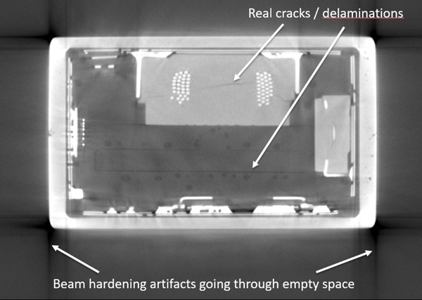
With many difficult samples it is often the case that the best scanning technique and software corrections can’t perfectly fix every image artifact and the CT analyst has to interpret a non-ideal CT scan volume. When this happens it requires a good understanding of what forms an artifact can take so there is no misinterpretation where the artifact is falsely labeled as a crack or other defect. Figure 2 shows two different cross sectional images of the same LED lightbulb sample. Both show beam hardening artifacts that are clearly in line with flat segments of dense material but the artifacts indicated on the left go through empty space while on the right the dark shadows continue into a lower density housing material.
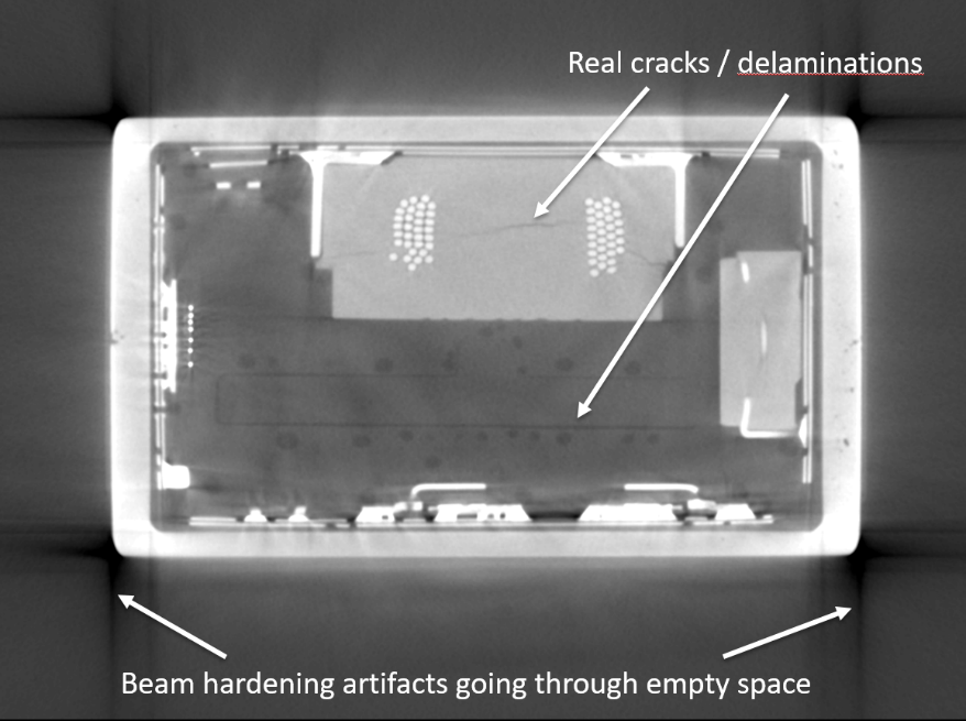
Figure 2: Examples of beam hardening “shadow” artifacts along the edges of flat, dense surface boundaries. Note that artifacts are especially accentuated along long, flat surfaces versus rounded or irregular objects.
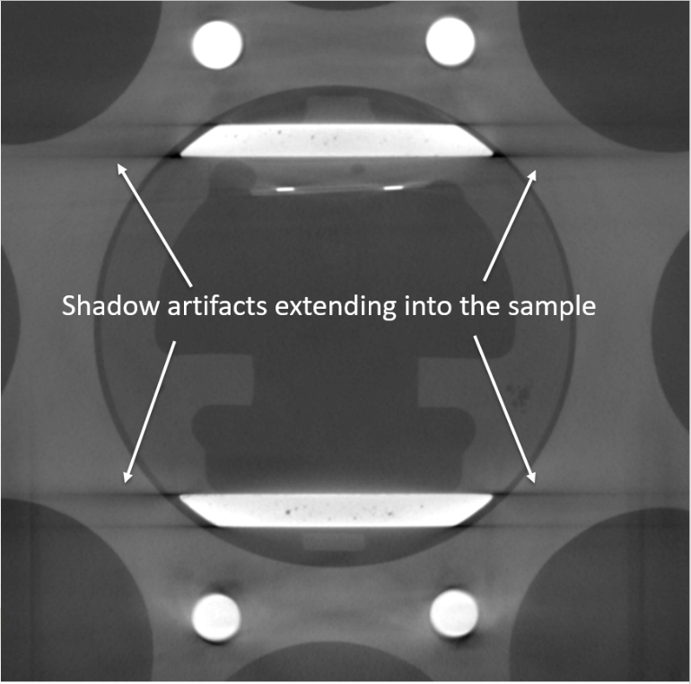
Very often there is still valuable data within the artifact, however, it is typically necessary to window level the image to provide adequate viewing within the specific region of the artifact. Often this little adjustment of the histogram can allow the interpreter to judge whether or not an artifact is obscuring anything important. However, sometimes the streaks or shadows are so bad that entire regions are rendered un-interpretable. In these cases it is impossible to verify if there is a defect in a critical area without potentially rescanning the sample or using an alternative analysis technique such as ultrasonic or other testing method.
Summary
Image artifacts in a CT scan are often a matter of fact in samples with multiple different materials or widely varying material thicknesses. Therefore, it benefits the CT analyst to understand where they come from and what they look like to get the most out of this valuable analysis technique.