X-ray Inspection of a 3D Printed Turbine Blade
Computed Tomography for Aerospace
Let’s take a closer look at 3D printed parts and how 3D computed tomography can be used to inspect these parts.
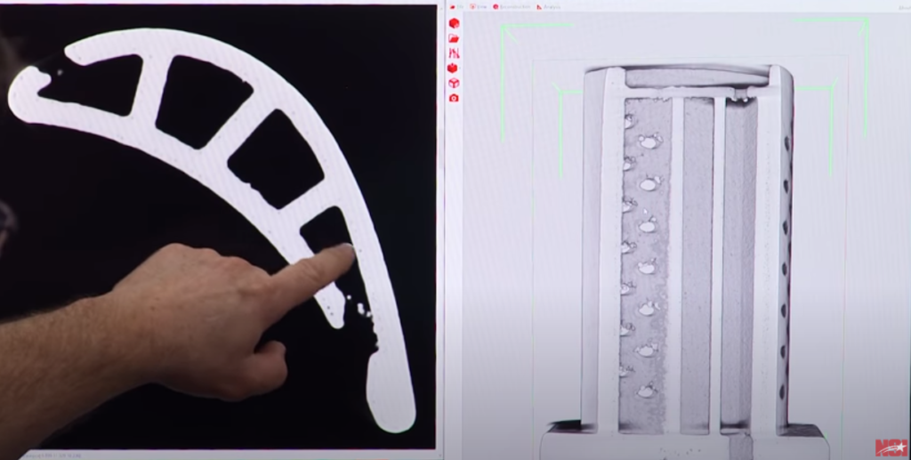
This is a simple model of a turbine blade that is printed out of aluminum, and is something you may find in a turbine engine. The purpose of scanning this additive manufactured part would be to validate dimensions, look for accuracy or identify defects with the part.
There are many different types of additive manufactured parts. Although plastic is the most common amongst consumers, we have seen parts printed out of titanium, nickel and other metals for special applications. We have even seen a 3D printed part made from paper.
For this sample we use 3D computed tomography to get a clear view of the internals. It is important to note that additive manufactured parts do not necessarily require a different approach or technique to scan. We can set up the scan the same way we would set it up if it is a cast or molded part. It has less to do with how it is made and more to do with what it is made of.
It is important to always take time to optimize the system for the particular part being scanned. First, center the part in the detector and then work on the penetration and contrast by moving the tube and the detector to the appropriate distance for optimization. When the scan starts the part will spin 360 degrees and the system will take over 1000 radiographs of the part. After the images are taken, the proprietary software stitches the images together to form a 3D image. The image can be sliced through on multiple axis and rotated in every angle.
Now that we have our scan data, let’s take a look at the results. As we slice through the data, we can see some voiding which would be a lack of material that can easily be seen because it shows darker.
We can also see some extra material sitting along the edge and all of the way down the side of the part. The extra material is concerning because it can cause problems with airflow issues which could cause the part to overheat, cause imbalance or create dimensional inaccuracies.
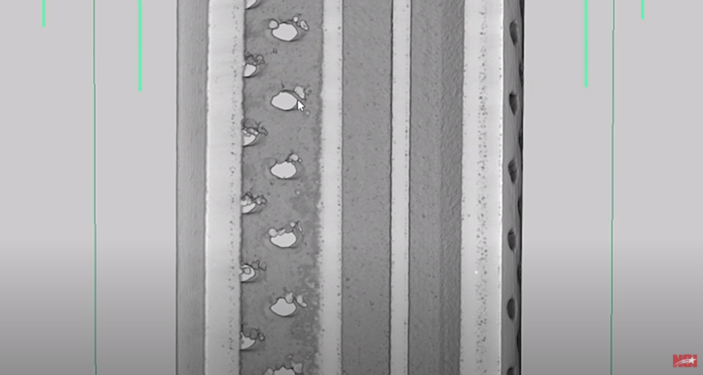
Another important part of inspecting a 3D printed part is identification of inclusions, or more dense material compared to the parent material. As we look closer into the dimensions we can perform a CAD comparison. A CAD comparison is when we compare the scan data to the original CAD data. to see the actual shape and size it is supposed to be vs the size of the 3D image.
