Bringing Additive Manufacturing into the Mainstream with CT Scanning
Additive manufacturing (AM) has rapidly expanded into nearly all industries with projections of growth continuing in the double digits for the next decade. AM carries with it the ability to expand product performance, reduce design-to product-cycle times and drive down total product cost. AM methods and technology continue to advance in both capabilities and quality while providing more options in metals and polymers as well as many hybrid materials. With AM, yesterday’s impossible is truly today’s opportunity.
One common denominator across all areas of AM is the need for qualification of the AM process and product. The performance of some AM products can be critical in sustaining human life as well as assuring the function and protection of equipment valued at millions of dollars. Flight-critical metal AM products are rapidly replacing products manufactured with conventional manufacturing processes, such as castings, forgings and weldments. Cast medical implants are being replaced with metal and polymer-based AM products with characteristics that make them superior in their biological attachment within the body while employing materials optimal for biocompatibility. Numerous other industries have successfully begun to employ the use of AM in their manufacturing of performance-critical products. With any relatively new or changing process, there can be a painful learning curve as we gain the knowledge of the controlling process variables and their optimization for manufacturing productivity and quality. AM is not exempt from these growing pains. However, there are technologies that have dramatically helped accelerate the development process.
Shifting of technologies for evaluation of product integrity
When we pick up an AM product, visual and other surface evaluation methods provide some general assessment as to whether we have a quality product. But what lies under that surface is often what is most critical. Typical non-destructive testing methods used for casting inspection may not be appropriate for some of the AM processes and alternative methods will need to be employed. Ultrasonic testing (UT) can sometimes be used in evaluating a product’s internal integrity, yet many AM product geometries, surface conditions and grain structures do not lend themselves to the UT process.
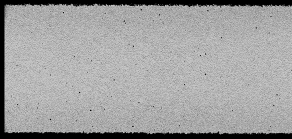

Digital radiography (DR) and film radiography have been found to be successful in the evaluation of some AM metal products but they don’t have the image quality to adequately identify some of the common AM discontinuities in other parts. For most critical metal AM products, computed tomography (CT) has become the go-to technology for evaluating parts for internal integrity. Figure 1 compares DR and CT images of a metal AM product, displaying levels of clarity that CT provides for detecting small discontinuities.
Validation of Product Integrity
Any method used to evaluate a product for internal integrity should be qualified and validated for a specific product. A common method of qualifying a CT technique and validating product integrity is by creating multiple reference quality indicator (RQI) parts.
When possible, these RQIs are printed with intentionally generated discontinuities and anomalies representing what could potentially occur within the specific AM process. The RQI is typically made from either an actual product, a section of a product or a close representation of a product. A minimum of two RQIs are typically created and CT scanned.
One of the RQIs is then cross-sectioned, typically in multiple areas to confirm the type and size of features correlate with the CT scan data. Additional discontinuities or anomalies identified in either the CT scan or the cross sections are cross-validated. This process helps understand and define the limitation parameters for detectability using CT. The remaining RQI should be used to continually monitor the performance of the CT scan process over time.
Growing advances of in-Situ monitoring
Significant advancements have been made in the area of in-situ monitoring of AM during the printing cycle. Many metal powder bed fusion (PBF) systems are equipped with one or multiple types of in-situ sensors monitoring each fusion layer of the melt pool for variation or anomalies that may contribute to anon-optimal condition within the product. Extensive work is being done for it to be capable of spatially plotting this data in a three-dimensional format tied to the geometry of the product. This data may be very useful, but only when it can first be correlated to a specific outcome within the product, such as a discontinuity. This correlation can be valuable in predicting the product quality during the build process.
Initially, the painstakingly slow and incomplete process of cross-sectioning a product was the primary way of providing this type of correlation. For many AM products, CT has now become the method of choice in validating the in-situ process and making the above correlations. The layer-by-layer data collected from in-situ detectors can be used to generate a 3D data set of information that can be spatially correlated to the 3D CT scan and any associated product anomalies. This provides a powerful method of assessing what type of discontinuity a specific in-situ monitored event produced within the product and its precise location.
The layer-by-layer data collected from in-situ detectors can be used to generate a 3D data set of information that can be spatially correlated to the 3D CT scan and any associated product anomalies. This provides a powerful method of assessing what type of discontinuity a specific in-situ monitored event produced within the product and its precise location.
This combined approach can help provide a higher level of confidence in the in-situ monitoring. The ideal is that the in-situ monitoring process would consistently identify any event within the build that will cause an unacceptable condition and then either stop the print or correct the condition and continue.
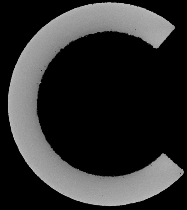
This could drastically reduce the amount of scrap or reworked product that is identified later with CT inspection and, for some products, may be able to reduce inspection to a sample or eliminate CT inspection requirements. Any reduction in inspection should be addressed cautiously when relying on only in-situ monitoring technologies as they also have their own tolerances of measurement and detection. The need for further improvement is still evident by the simple observation that, even when some in-situ monitoring predicts no rejectable discontinuities, some parts are still found to contain defects detected by CT scans (see Figure 2).
Some critical products will always require 100 per cent inspection using CT, but the more we can learn from the combination of CT and in situ monitoring, the more likely a case can be made for a consideration of process and product CT sampling.
Considerations in the use of mechanical property test coupons
Another method of monitoring the effectiveness and quality of a PBF AM build is through using destructive testing of coupons to assess a product’s mechanical properties. However, even when shear, compression and fatigue sample coupons are printed at the same time on the same build set as a part or parts, product geometries and wall thicknesses often vary significantly from the coupons. This approach, therefore, does not always produce a valid representation of the material properties of the product itself but can still provide some useful data.
It is, therefore, recommended that metallography and mechanical property testing be performed on the representative coupons as well as on actual product to identify if there is an adequate representation from the coupons.
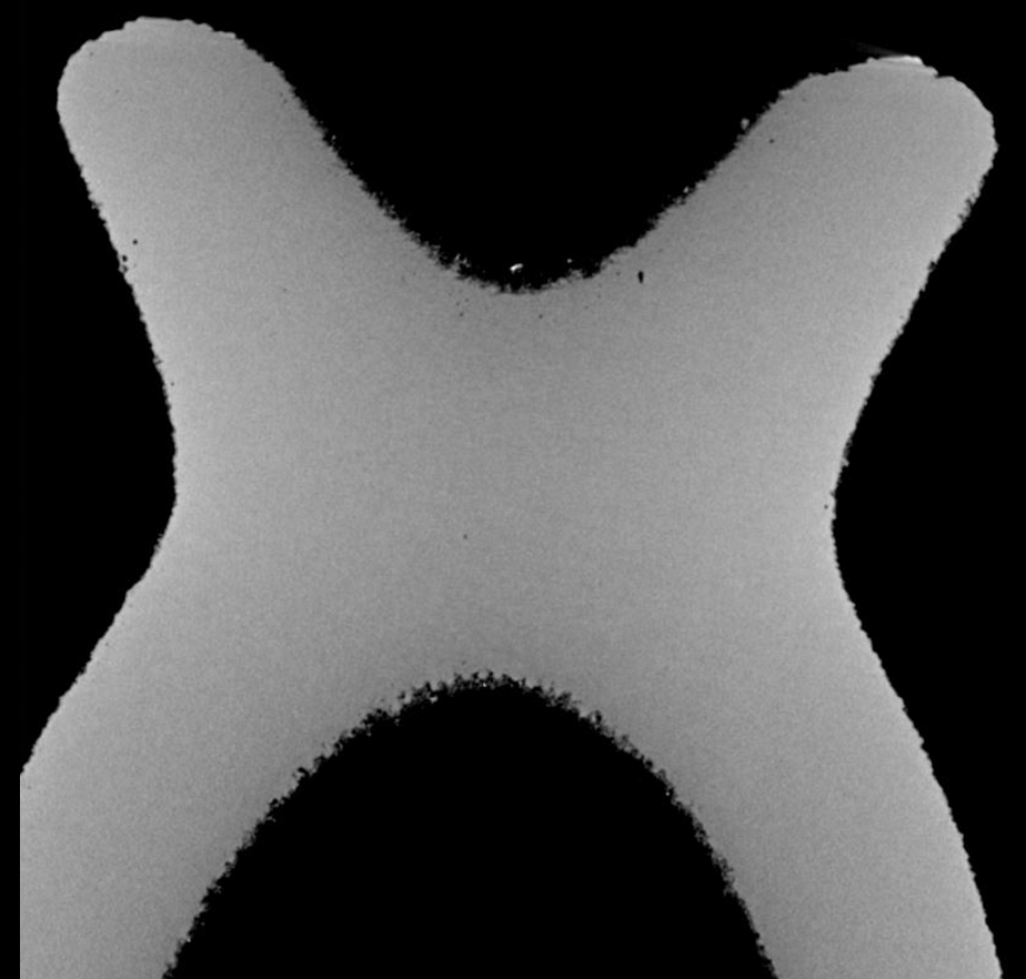
It’s also becoming more common practice that all test coupons be CT scanned before testing to identify the types of discontinuities that are present, as this can dramatically impact the mechanical property results (see Figure 3). A new hybrid version of this process is in-situ CT. In this process, the load cell equipment is integrated within the CT system. Multiple CT scans are performed while the sample coupons are under load, providing the ability to capture 3D data of the sample’s internal structure movement through the point of failure.
Metrology of complex AM products
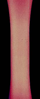
Many AM product designs are taking on complex geometries with internal features and chambers that are not accessible for conventional measurement methods, such as contact coordinate measurement machines (CMM). CT is now successfully solving this problem and is used to retrieve internal and external metrology data of AM products for product acceptance (see Figure 4), while also providing data in monitoring build variability within a specific AM machine. Some innovative PBF AM equipment providers are also providing means of retrieving metrology data layer by layer during a product build. CT can be further used to validate and monitor this process by comparing the final as-built data to the CT scan full metrology data.
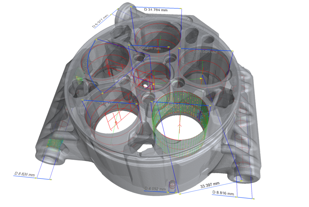
Figure 4
Upcoming uses of CT in AM
CT is beginning to be used to validate and further improve upon AM product design and print simulation models by performing an as-built CT scan of the product and comparing it to the original simulation print model.
Conclusion
CT is increasingly being applied in assisting the AM manufacturing process in the evaluation of product integrity, in-situ monitoring validation, product qualification, process monitoring, metrology, HIP processing qualification and print simulation model design validation and improvement.
As AM processes and methods continue to evolve, the application and capabilities of CT and other technologies are expected to continue to grow to support the rapidly expanding demands of one of the most exciting manufacturing processes of all time.