CT Inspection of an Electrical Connector
Computed Tomography for Electronics
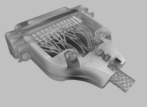
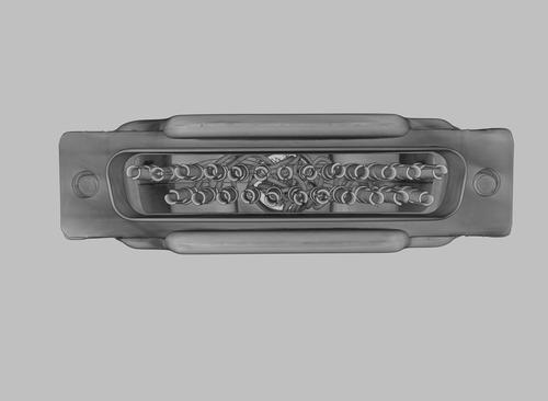
Electrical connectors are commonly evaluated with digital radiography. Connectors designed with multiple pins and complex geometries make it more difficult to adequately inspect due to the many superimposed features. CT scanning of this type of product provides a much higher probability of detection when evaluating product for wire fraying and nicking, wire insertion position, crimp joint integrity, pin positioning, foreign objects and debris (FOD) as well as insulation integrity and position. Additionally, even the cast connector shell can be evaluated for porosity, shrinkage and other casting discontinuities.
Look at the orientation of these pins, a lot of them are placed in different directions. This may or may not have impact on the functionality because it is a round hole, however when it comes to the orientation of the other end that it will be plugged into, sometimes the wires end up in closer proximity because they are rotated in a different direction. At a minimum, it’s a potential for a problem.
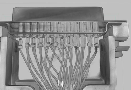
Before inserting the wire into the electrical pin, the wire insulation must be trimmed off. After the wire is inserted into the electrical pin, then it can be crimped. In this region you have the potential to nick the wires when the insulation is stripped off and that can cause problems. Nicked wires may not insert properly, because they may not be fully inserted and crimped making them less likely to stay put. This can cause fraying wires. Sometimes when the wires are frayed they could stick out and potentially touch the other wires. If we change the window leveling in CT to create more transparency in the image, we can discern the actual insulation levels.