Ensure your 3D Printed Part Meets Standards for Quality and Function
Computed Tomography for Additive Manufacturing
3D printing is moving from visual non-functional prototyping, to a technology that satisfies real-world applications or production requirements. Since the requirements for 3D printed parts are becoming significantly more demanding, the industry is searching for ways to validate and analyze their products. Industrial CT scanning is able to validate internal geometry and defects within a part without destroying the part.
An industrial computed tomography (CT) scan can validate and qualify prototypes and the first printed parts for many different materials such as mold components, metal or plastic printed parts. CT scanning aids in manufacturing projects that require 100% validation of high value printed parts during production. Any failed parts or errors during production due to temperature change or stress, such as broken or chipped parts can be examined and identified quickly through CT scanning. Several different analyses can be run on the scanned part, including:
- Internal void analysis
- Reverse engineering
- Part-to-CAD comparison
- Internal and external geometry analysis
- And much more
In this part-to-CAD comparison, green shows the part is close to the CAD model, red is larger than the CAD, and blue is smaller than the CAD. Where the colors flatten out, the part is outside the parameters set for the analysis showing the pink and purple.
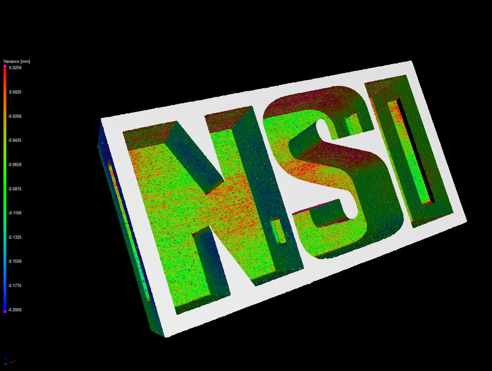
In this porosity analysis (plastic part) and this inclusion analysis (the Positive Metal NSI Logo). The software looks at the gray value of the voxels in the volume and determines if an area is a porosity or higher density inclusion. The defects that are detected can then be colorized so you can see the rough locations and size. There is an option to produce a spreadsheet with locations and sizes of defects for accept/reject decisions. You can also put accept/reject criteria in the software when you run the analysis and it will tell you if it passed or not.
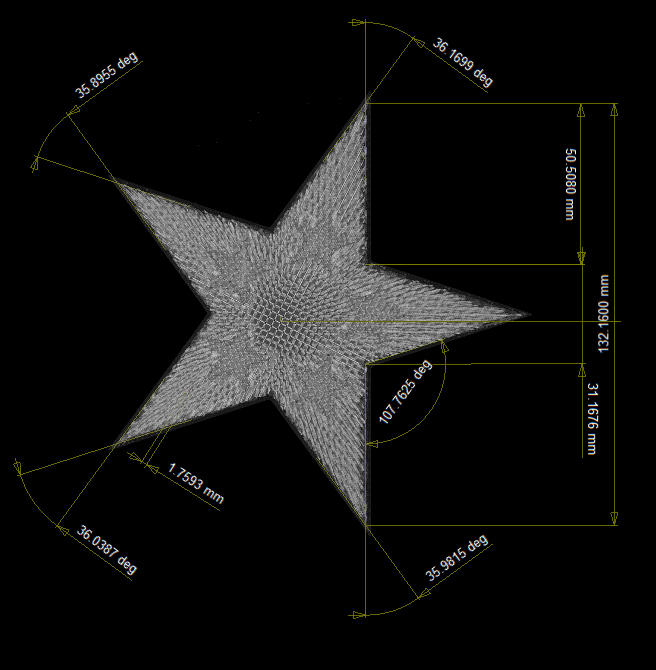
In an internal and external geometry analysis, first we fit features to the sample, i.e. plane, sphere, line, cylinder, and then the software can measure from those. We can also create features that are not fitted to the part, for some of the dimensions from point to point on the stars we measured from lines that we generated by intersecting two planes. We can also measure things like parallelism and concentricity.